
computer networks
8. Applied Networking for DevOps

On this page
- Networking for DevOps
- SSH
- SSH
- SSH
- Virtual Private Cloud
- AWS VPC
- AWS Regions
- AWS Regions & VPC
- AWS Availability Zones
- AWS Availability Zones
- AWS Availability Zones & VPC
- Types of VPC
- Default VPC
- AWS Subnets
- AWS VPC and Subnets
- Types of Subnets
- VPC Routing
- Internet Gateway
- NAT Gateway
- Firewalls
- Network ACLs
- Security Groups
- AWS Elastic Load Balancers
- AWS Elastic Load Balancers
- Application Load Balancer
- Application Load Balancer
- Application Load Balancer
- Application Load Balancer
- Application Load Balancer
- Application Load Balancer
- Network Load Balancer
- Network Load Balancer
- VPC Peering
- VPC Peering - Single Region
- VPC Peering - Cross Region
- VPC Peering
- VPC Peering
- Transit Gateway
- Transit Gateway Attachment
- Transit Gateway - Intra Region
- Transit Gateway - Cross Region
- Applied Networking for DevOps
Networking for DevOps
01
Notes
Chap 8
Networking in the Cloud
SSH
02
Notes
Secure Shell is a cryptographic network protocol that lets you securely connect to and control a remote machine over an unsecured network
You have a server running somewhere in a data centre could be Mumbai, Singapore, Virginia, anywhere. You want to run commands on that server. Install software, check logs, configure a service, deploy your application.
You are not physically sitting in front of that server. You are at your laptop. SSH gives you a secure terminal session on that remote machine.
Everything travels encrypted. Your commands going to the server encrypted. The server's output coming back encrypted. Anyone intercepting the traffic sees nothing useful.
SSH
03
Notes
SSH runs on port 22 by default a number worth remembering because you will configure firewall rules to allow SSH access constantly in cloud environments.
SSH supports two ways to authenticate password-based and key-based. Key-based is universal standard because passwords can be brute-forced.
Key-based authentication uses a pair of cryptographic keys - a private key and a public key.
The public key goes on the server in a file called authorized_keys. It is not secret.
The private key stays on your machine in your ~/.ssh/ directory. It is secret. Never share it. Never put it in a repository. Treat it like a password you can never change.
SSH
04
Notes
When you connect SSH uses your private key to prove your identity mathematically, without ever sending the key over the network. The server verifies using the public key. If they match access granted. No password needed.
SSH supports tunneling, allowing traffic to travel securely through an encrypted SSH connection. One common use of SSH tunneling is port forwarding, where traffic from one port is securely forwarded to another machine or service.
Using tunnelling you securely access resources that have no public exposure.
Virtual Private Cloud
05
Notes
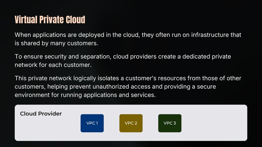
When applications are deployed in the cloud, they often run on infrastructure that is shared by many customers.
To ensure security and separation, cloud providers create a dedicated private network for each customer.
This private network logically isolates a customer’s resources from those of other customers, helping prevent unauthorized access and providing a secure environment for running applications and services.
Cloud Provider
VPC 1
VPC 2
VPC 3
AWS VPC
06

Notes
A Virtual Private Cloud (VPC) is a private, isolated network within AWS where you can launch and manage your cloud resources.
It gives you complete control over your networking environment like
Subnetting
Routing
Firewalls (NACLs, Security Grps)
Gateways
Each AWS account can have multiple VPCs.
AWS Regions
07
Notes
A Region is a geographic area where a cloud provider operates multiple data centers
Each Region contains multiple Availability Zones (AZs).
Regions help organizations meet data residency, compliance, and latency requirements.
Cloud providers operate Regions in different parts of the world so customers can deploy applications closer to their users.
When choosing a Region, consider factors such as latency, compliance, service availability, and cost.
AWS Global Infrastructure
AWS Regions & VPC
08
Notes
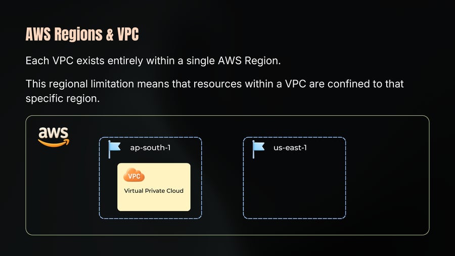
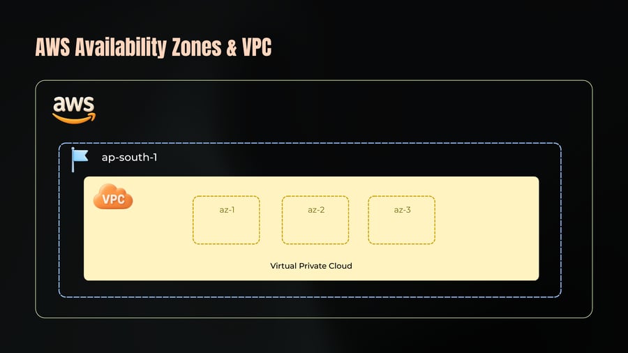
Each VPC exists entirely within a single AWS Region.
This regional limitation means that resources within a VPC are confined to that specific region.
AWS Availability Zones
09
Notes
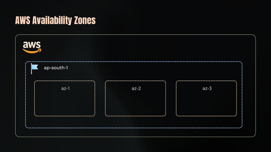
An Availability Zone (AZ) is one or more data centers within a cloud region.
Each AZ has its own power, networking, and infrastructure.
Multiple AZs in a region are connected through high-speed, low-latency networks.
Communication between AZs is encrypted and secure.
If one AZ experiences an outage, applications can continue running in another AZ.
Availability Zones are located far enough apart to reduce impact of local disruptions, but close enough (typically within 100 km / 60 miles) to provide fast and reliable communication between them.
AWS Availability Zones
10
Notes
ap-south-1
az-1
az-2
az-3
AWS Availability Zones & VPC
11
Notes
ap-south-1
VPC
az-1
az-2
az-3
Virtual Private Cloud
Types of VPC
12
Notes
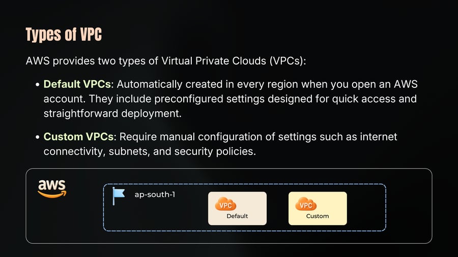
AWS provides two types of Virtual Private Clouds (VPCs):
• Default VPCs: Automatically created in every region when you open an AWS account. They include preconfigured settings designed for quick access and straightforward deployment.
• Custom VPCs: Require manual configuration of settings such as internet connectivity, subnets, and security policies.
Default VPC
13
Notes
Every region has one default VPC.
The default VPC is assigned a /16 CIDR block, specifically 172.31.0.0/16, offering 65,536 IP addresses.
For each availability zone in a region, a default subnet is created. Subnets are typically configured with a /20 mask.
An Internet Gateway is automatically attached to the default VPC which ensures that every subnet within the default VPC is public.
Default security groups and Network Access Control Lists (NACLs) are set up to manage and control traffic.
AWS Subnets
14
Notes
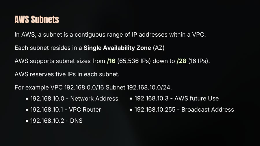
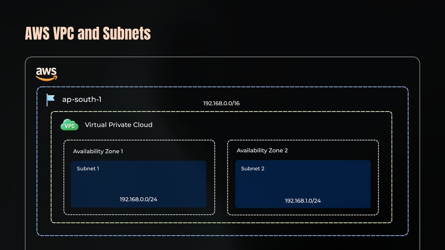
In AWS, a subnet is a contiguous range of IP addresses within a VPC.
Each subnet resides in a Single Availability Zone (AZ)
AWS supports subnet sizes from /16 (65,536 IPs) down to /28 (16 IPs).
AWS reserves five IPs in each subnet.
For example VPC 192.168.0.0/16 Subnet 192.168.10.0/24.
192.168.10.0 - Network Address
192.168.10.1 - VPC Router
192.168.10.2 - DNS
192.168.10.3 - AWS future Use
192.168.10.255 - Broadcast Address
AWS VPC and Subnets
15
Notes
ap-south-1
192.168.0.0/16
Virtual Private Cloud
Availability Zone 1
Subnet 1
192.168.0.0/24
Availability Zone 2
Subnet 2
192.168.1.0/24
Types of Subnets
16
Notes
ap-south-1
VPC
Virtual Private Cloud
Availability Zone 1
Subnet 1
Public
NAT Gateway
Availability Zone 2
Subnet 2
Private
Internate Gateway
VPC Routing
17
Notes
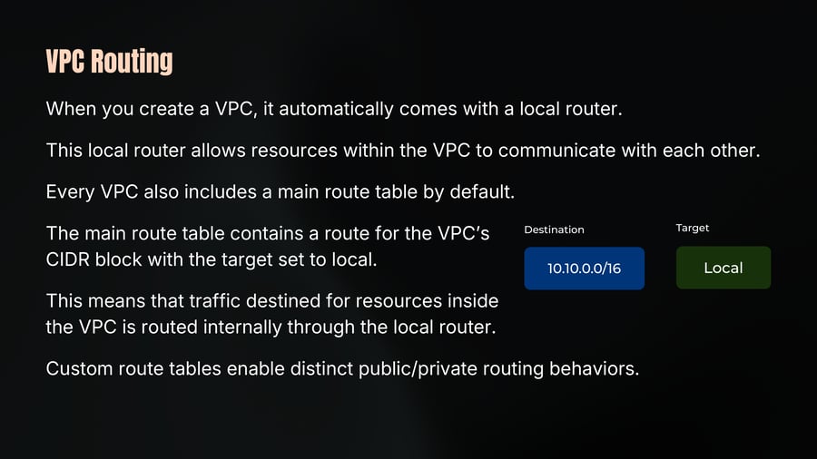
When you create a VPC, it automatically comes with a local router.
This local router allows resources within the VPC to communicate with each other.
Every VPC also includes a main route table by default.
The main route table contains a route for the VPC’s CIDR block with the target set to local.
This means that traffic destined for resources inside the VPC is routed internally through the local router.
Custom route tables enable distinct public/private routing behaviors.
Internet Gateway
18
Notes
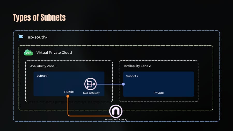
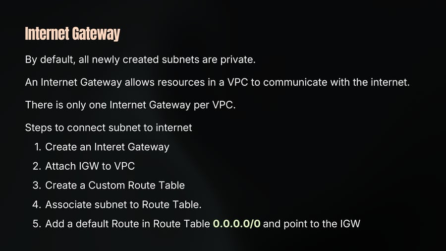
By default, all newly created subnets are private.
An Internet Gateway allows resources in a VPC to communicate with the internet.
There is only one Internet Gateway per VPC.
Steps to connect subnet to internet
1. Create an Interet Gateway
2. Attach IGW to VPC
3. Create a Custom Route Table
4. Associate subnet to Route Table.
5. Add a default Route in Route Table 0.0.0.0/0 and point to the IGW
NAT Gateway
19
Notes
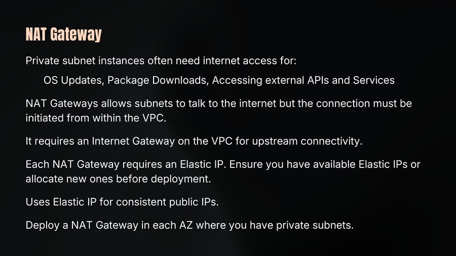
Private subnet instances often need internet access for:
OS Updates, Package Downloads, Accessing external APIs and Services
NAT Gateways allows subnets to talk to the internet but the connection must be initiated from within the VPC.
It requires an Internet Gateway on the VPC for upstream connectivity.
Each NAT Gateway requires an Elastic IP. Ensure you have available Elastic IPs or allocate new ones before deployment.
Uses Elastic IP for consistent public IPs.
Deploy a NAT Gateway in each AZ where you have private subnets.
Firewalls
20
Notes
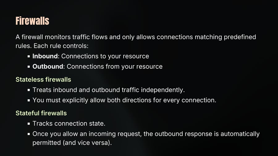
A firewall monitors traffic flows and only allows connections matching predefined rules. Each rule controls:
Inbound: Connections to your resource
Outbound: Connections from your resource
Stateless firewalls
Treats inbound and outbound traffic independently.
You must explicitly allow both directions for every connection.
Stateful firewalls
Tracks connection state.
Once you allow an incoming request, the outbound response is automatically permitted (and vice versa).
Network ACLs
21
Notes
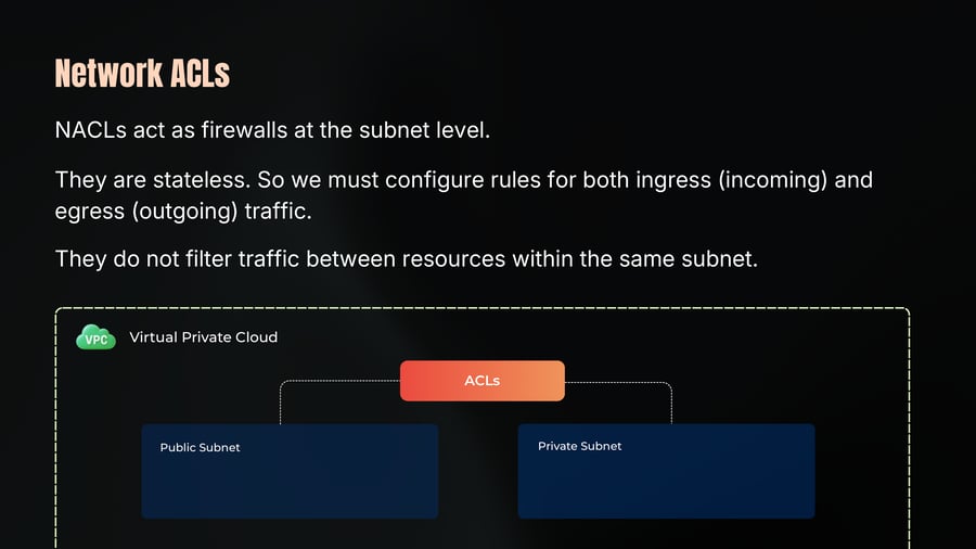
NACLs act as firewalls at the subnet level.
They are stateless. So we must configure rules for both ingress (incoming) and egress (outgoing) traffic.
They do not filter traffic between resources within the same subnet.
Security Groups
22
Notes
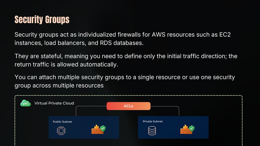
Security groups act as individualized firewalls for AWS resources such as EC2 instances, load balancers, and RDS databases.
They are stateful, meaning you need to define only the initial traffic direction; the return traffic is allowed automatically.
You can attach multiple security groups to a single resource or use one security group across multiple resources
VPC Virtual Private Cloud
ACLs
Public Subnet
Private Subnet
AWS Elastic Load Balancers
23
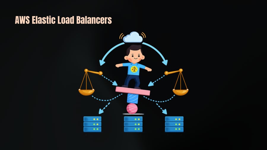
AWS Elastic Load Balancers
24
Notes
ELB Acts as a single entry point for client requests.
Distributes incoming traffic across multiple servers.
Prevents one server from becoming overloaded.
Improves
Availability
Scalability
Reliability
AWS offers two main ELB types.
Application Load Balancer
25
Notes
Operates at Layer 7 (HTTP/HTTPS).
Supports advanced request routing:
Path-based routing (e.g., /api vs /images)
Host-based routing (route by domain/subdomain)
Query-string-based routing
Can modify HTTP headers before forwarding requests.
Supports multiple load balancing algorithms like Round robin, least outstanding requests, weighted random.
Application Load Balancer
26
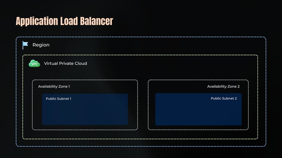
Notes
Region
VPC Virtual Private Cloud
Availability Zone 1
Public Subnet 1
Availability Zone 2
Public Subnet 2
Application Load Balancer
27
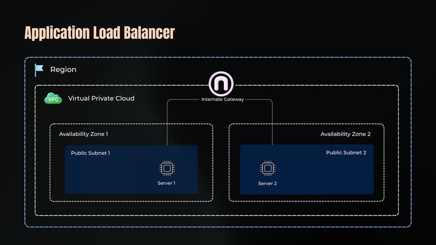
Notes
Region
VPC Virtual Private Cloud
Internate Gateway
Availability Zone 1
Availability Zone 2
Public Subnet 1
Public Subnet 2
Server 1
Server 2
Application Load Balancer
28
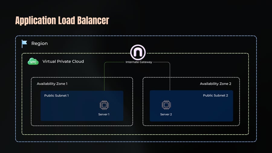
Notes
Region
Virtual Private Cloud
Internate Gateway
Availability Zone 1
Availability Zone 2
Public Subnet 1
Public Subnet 2
Server 1
Server 2
Application Load Balancer
29
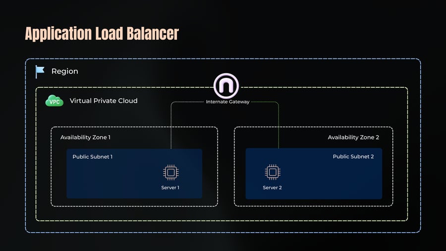
Notes
Region
VPC Virtual Private Cloud
Internate Gateway
Availability Zone 1
Availability Zone 2
Public Subnet 1
Public Subnet 2
Server 1
Server 2
Application Load Balancer
30
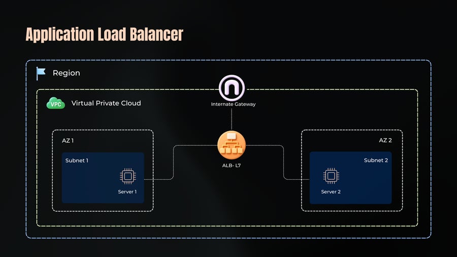
Notes
Region
VPC
Virtual Private Cloud
Internate Gateway
ALB- L7
AZ 1
Subnet 1
Server 1
AZ 2
Subnet 2
Server 2
Network Load Balancer
31
Notes
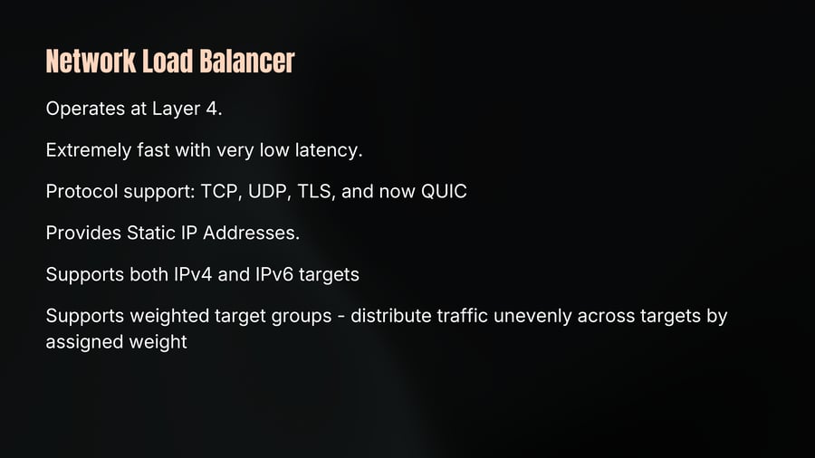
Operates at Layer 4.
Extremely fast with very low latency.
Protocol support: TCP, UDP, TLS, and now QUIC
Provides Static IP Addresses.
Supports both IPv4 and IPv6 targets
Supports weighted target groups - distribute traffic unevenly across targets by assigned weight
Network Load Balancer
32
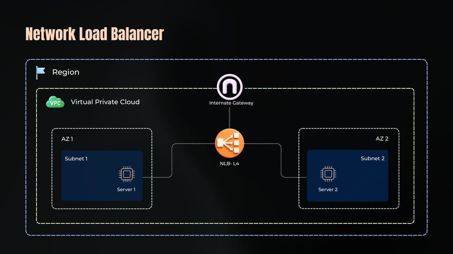
Notes
Region
VPC
Virtual Private Cloud
Internate Gateway
NLB- L4
AZ 1
Subnet 1
Server 1
AZ 2
Subnet 2
Server 2
VPC Peering
33
Notes
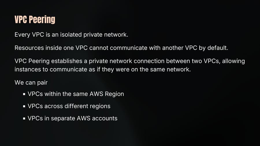
Every VPC is an isolated private network.
Resources inside one VPC cannot communicate with another VPC by default.
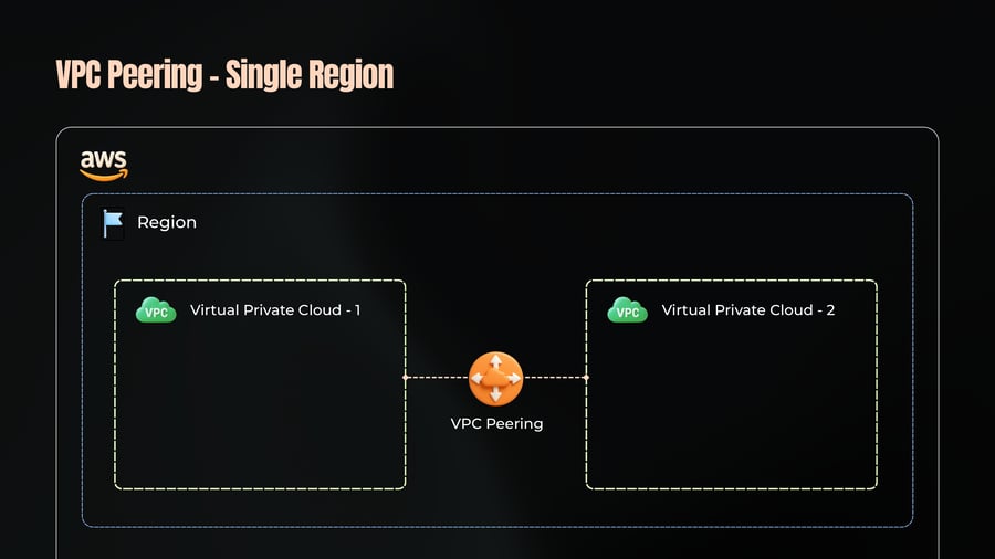
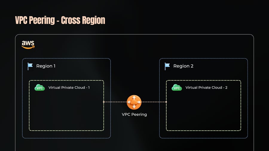
VPC Peering establishes a private network connection between two VPCs, allowing instances to communicate as if they were on the same network.
We can pair
VPCs within the same AWS Region
VPCs across different regions
VPCs in separate AWS accounts
VPC Peering - Single Region
34
Notes
Region
Virtual Private Cloud - 1
VPC Peering
Virtual Private Cloud - 2
VPC Peering - Cross Region
35
VPC Peering
36
Notes
Steps to peer VPCs
Request Peering
Accept Peering
Configuring Route Tables
VPC Peering is non-transitive.
If VPC1 peers with VPC2, and VPC2 peers with VPC3, VPC1 cannot reach VPC3 through VPC2.
Each pair requires its own peering connection.
VPC Peering
37
Notes
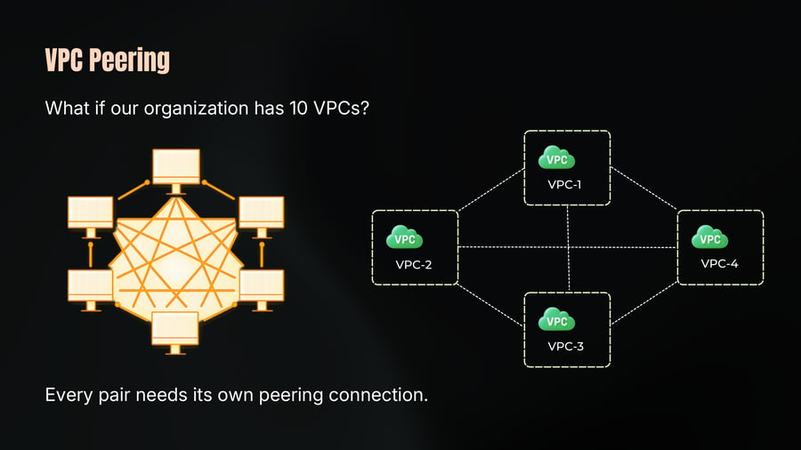
What if our organization has 10 VPCs?
Every pair needs its own peering connection.
Transit Gateway
38
Notes
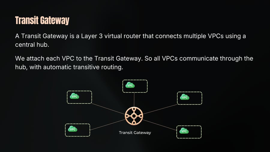
A Transit Gateway is a Layer 3 virtual router that connects multiple VPCs using a central hub.
We attach each VPC to the Transit Gateway. So all VPCs communicate through the hub, with automatic transitive routing.
Transit Gateway Attachment
39
Notes
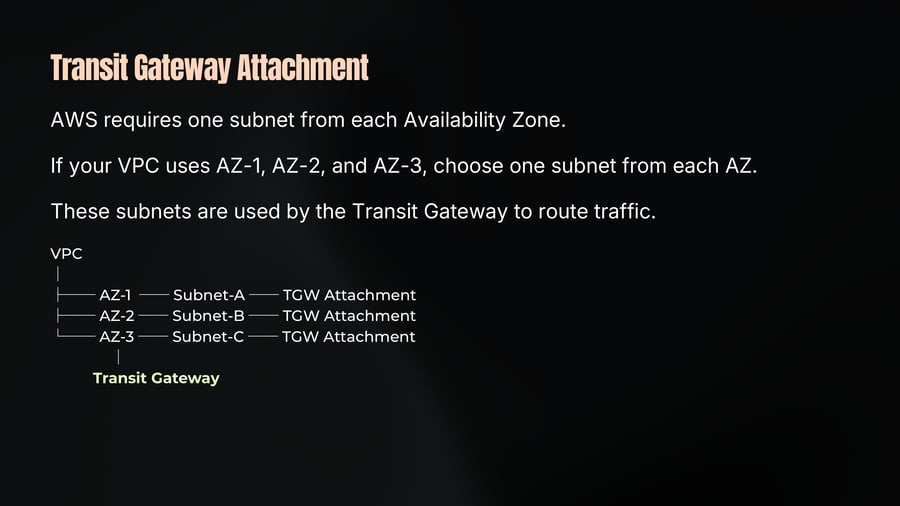
AWS requires one subnet from each Availability Zone.
If your VPC uses AZ-1, AZ-2, and AZ-3, choose one subnet from each AZ.
These subnets are used by the Transit Gateway to route traffic.
Transit Gateway - Intra Region
40
Notes
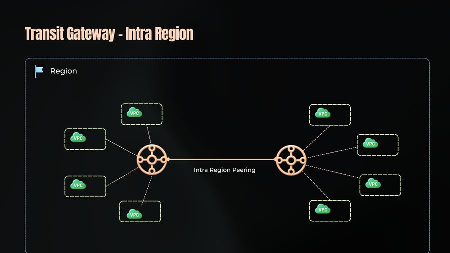
Region
Intra Region Peering
Transit Gateway - Cross Region
41
Notes
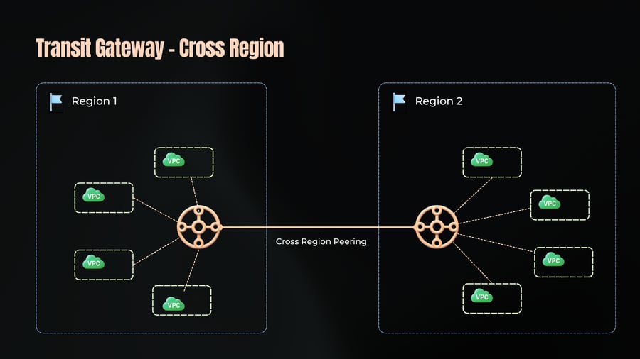
Region 1
Region 2
Cross Region Peering
Applied Networking for DevOps
42
Notes
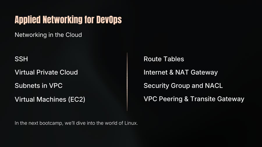
Networking in the Cloud
SSH
Virtual Private Cloud
Subnets in VPC
Virtual Machines (EC2)
Route Tables
Internet & NAT Gateway
Security Group and NACL
VPC Peering & Transite Gateway
In the next bootcamp, we’ll dive into the world of Linux.