

On this page
- Network Models
- Why We Need Models
- Why We Need Models
- Who Defines Standards
- OSI Model
- OSI Model
- OSI Layers
- OSI Layers
- OSI Layers
- OSI Layers
- OSI Layers
- OSI Layers
- TCP/IP Model
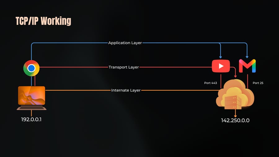
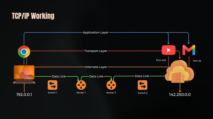
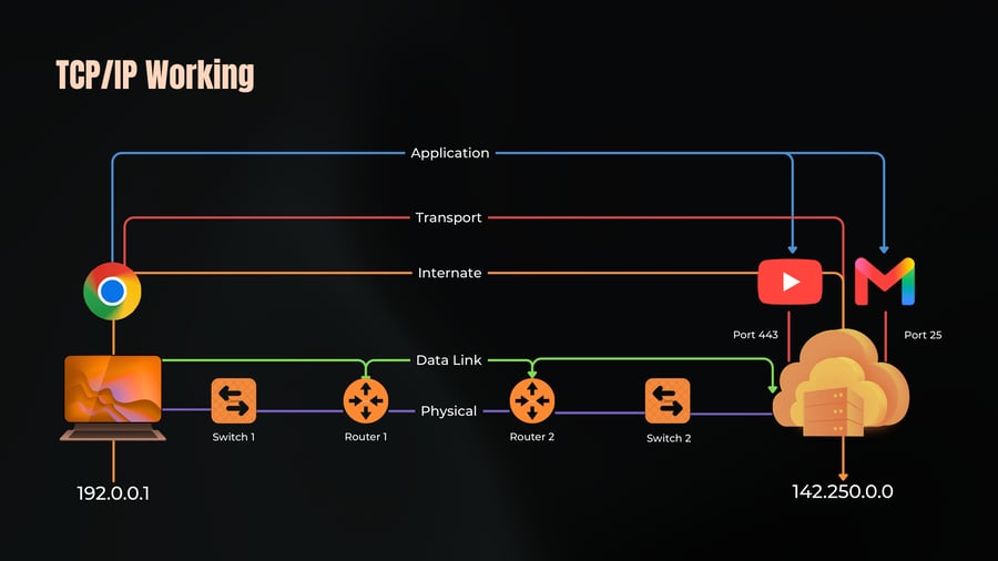
- TCP/IP Layers
- TCP/IP Working
- TCP/IP Working
- TCP/IP Working
- TCP/IP Working
- TCP/IP Working
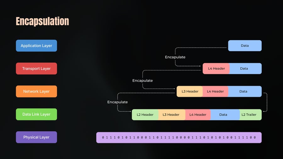
- Encapsulation
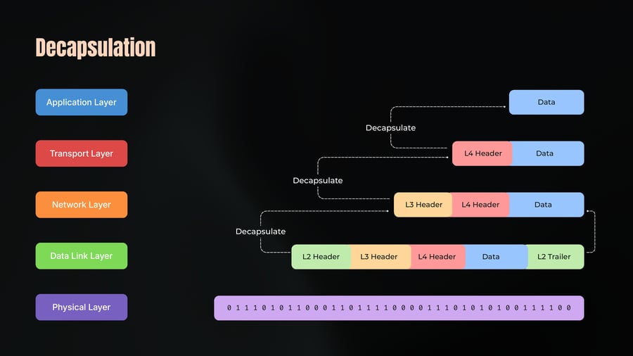
- Decapsulation
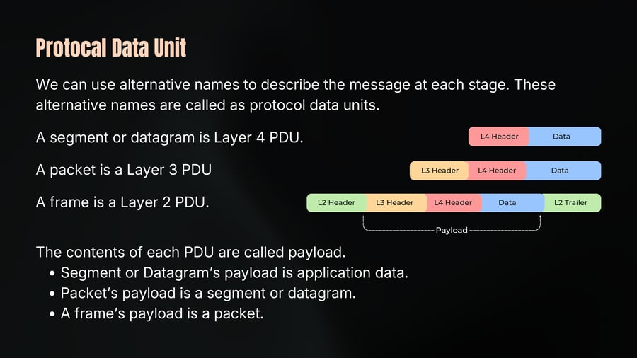
- Protocal Data Unit
- Message Delivery
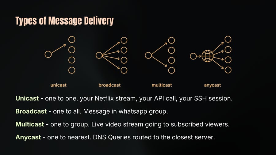
- Types of Message Delivery
- Anycast
- Network Models
Network Models
01
Notes
Chap 2
The Language of Communication
Why We Need Models
02
Notes
You are watching this bootcamp on Youtube.
You opened video your phone. That request somehow leaves your device, travels through Wi-Fi, crosses the internet, reaches a server in some data center, gets processed, and a data comes back - all in under few seconds.
Your phone was made by Apple. The server runs Linux. The router in your house is from a completely different manufacturer. The ISP's equipment is different again.
How do they all understand each other? The answer is models.
In the early days of networking, every company built their own system - their own cables, their own rules, their own way of sending data. And none of them could talk to each other.
Why We Need Models
03
Notes
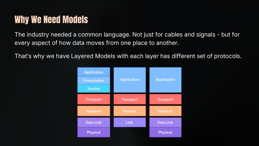
The industry needed a common language. Not just for cables and signals - but for every aspect of how data moves from one place to another.
That’s why we have Layered Models with each layer has different set of protocols.
Who Defines Standards
04
Notes
Most networking standards are developed by independent standard organization, not by a single vendor, with participation from engineers at many companies.
The first one is IEEE (Institute of Electrical and Electronics Engineers)
It develops many technologies used on the local area networks.
Ethernet (802.3)
Wi-Fi (802.11)
Second is IETF (Internet Engineering Task Force)
It is open committed and defines protocols used on the internet.
OSI Model
05
Notes
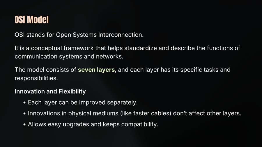
OSI stands for Open Systems Interconnection.
It is a conceptual framework that helps standardize and describe the functions of communication systems and networks.
The model consists of seven layers, and each layer has its specific tasks and responsibilities.
Innovation and Flexibility
Each layer can be improved separately.
Innovations in physical mediums (like faster cables) don't affect other layers.
Allows easy upgrades and keeps compatibility.
OSI Model
06
Notes
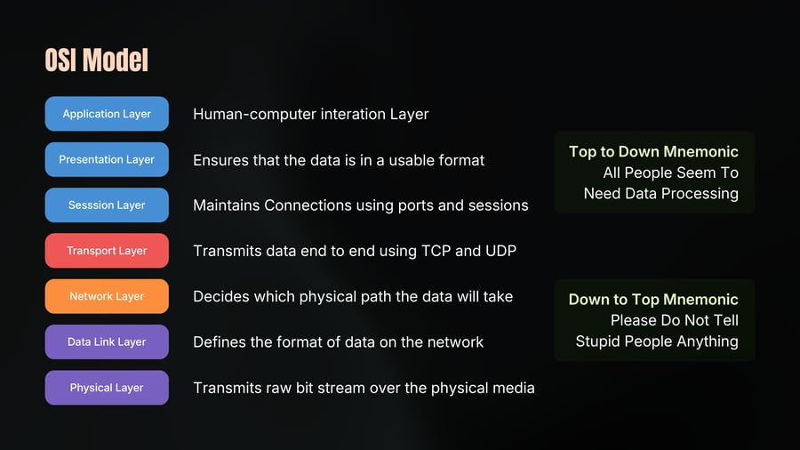
Application Layer
Human-computer interation Layer
Presentation Layer
Ensures that the data is in a usable format
Top to Down Mnemonic
All People Seem To
Need Data Processing
Sesssion Layer
Maintains Connections using ports and sessions
Transport Layer
Transmits data end to end using TCP and UDP
Network Layer
Decides which physical path the data will take
Down to Top Mnemonic
Please Do Not Tell
Stupid People Anything
Data Link Layer
Defines the format of data on the network
Physical Layer
Transmits raw bit stream over the physical media
OSI Layers
07
Notes
Application Layer
The softwares which interact one human to another works in application layer.
Example: Browsers.
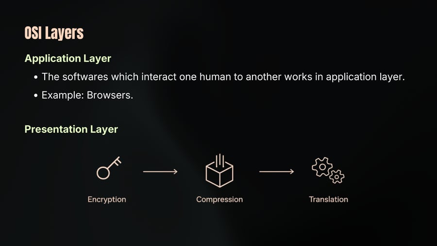
Presentation Layer
Encryption
Compression
Translation
OSI Layers
08
Notes
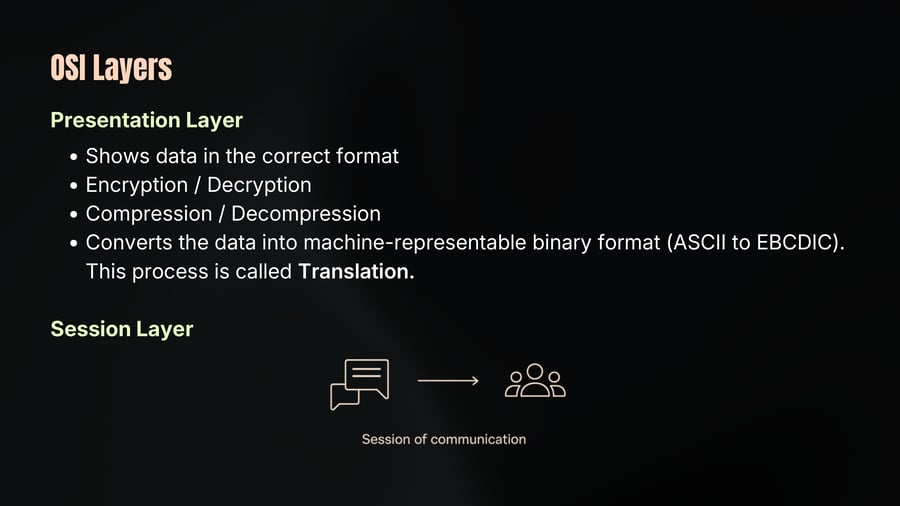
Presentation Layer
Shows data in the correct format
Encryption / Decryption
Compression / Decompression
Converts the data into machine-representable binary format (ASCII to EBCDIC).
This process is called Translation.
Session Layer
Session of communication
OSI Layers
09
Notes
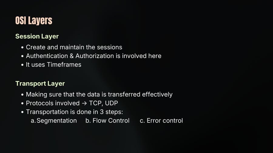
Session Layer
Create and maintain the sessions
Authentication & Authorization is involved here
It uses Timeframes
Transport Layer
Making sure that the data is transferred effectively
Protocols involved → TCP, UDP
Transportation is done in 3 steps:
a. Segmentation b. Flow Control c. Error control
OSI Layers
10
Notes
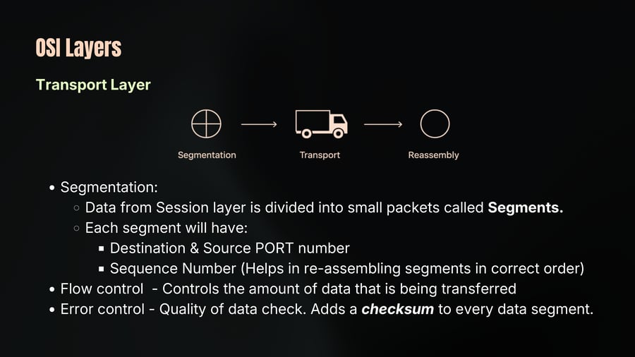
Transport Layer
Segmentation:
Data from Session layer is divided into small packets called Segments.
Each segment will have:
Destination & Source PORT number
Sequence Number (Helps in re-assembling segments in correct order)
Flow control - Controls the amount of data that is being transferred
Error control - Quality of data check. Adds a checksum to every data segment.
OSI Layers
11
Notes
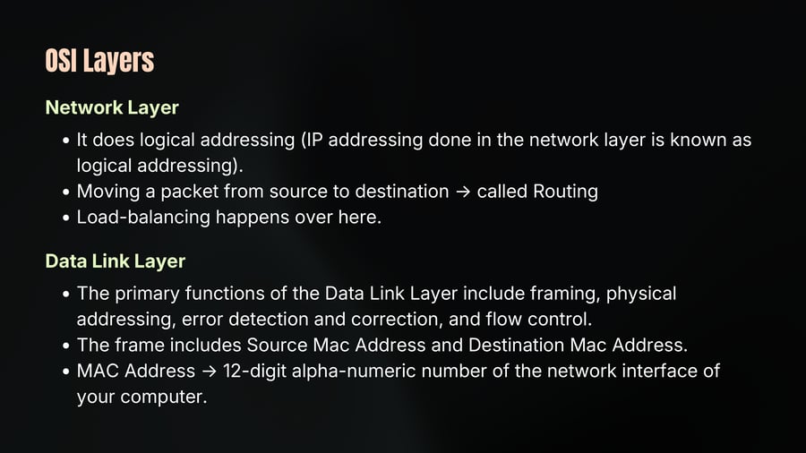
Network Layer
It does logical addressing (IP addressing done in the network layer is known as logical addressing).
Moving a packet from source to destination → called Routing
Load-balancing happens over here.
Data Link Layer
The primary functions of the Data Link Layer include framing, physical addressing, error detection and correction, and flow control.
The frame includes Source Mac Address and Destination Mac Address.
MAC Address → 12-digit alpha-numeric number of the network interface of your computer.
OSI Layers
12
Notes
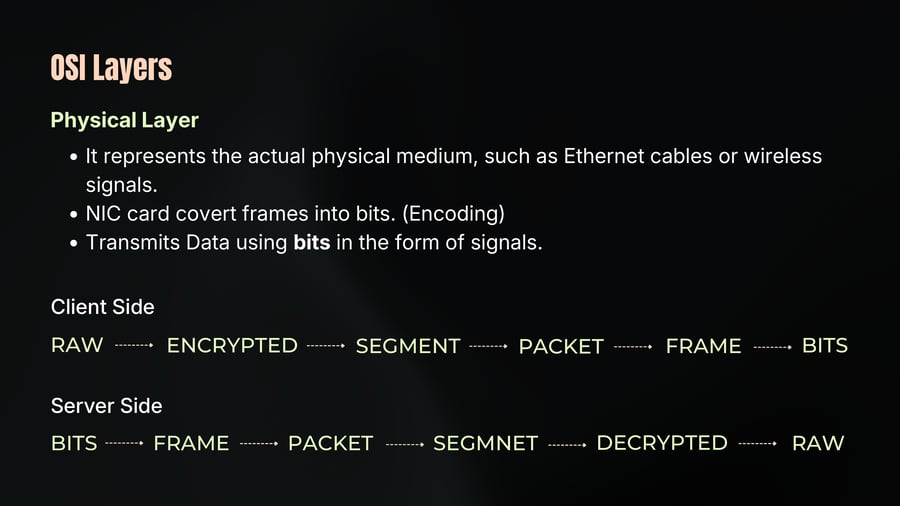
Physical Layer
It represents the actual physical medium, such as Ethernet cables or wireless signals.
NIC card covert frames into bits. (Encoding)
Transmits Data using bits in the form of signals.
Client Side
RAW -------> ENCRYPTED -------> SEGMENT -------> PACKET -------> FRAME -------> BITS
Server Side
BITS -------> FRAME -------> PACKET -------> SEGMNET -------> DECRYPTED -------> RAW
TCP/IP Model
13
Notes
TCP/IP stands for Transmission Control Protocol/Internet Protocol developed by ARPA.
It is the set of communication protocols used on the Internet and similar computer networks.
It provides end-to-end data communication.
It contains five layers and all the functionalities are organized in these five layers.
Application, Transport, Internet, Date Link, Physical.
TCP/IP Layers
14
Notes
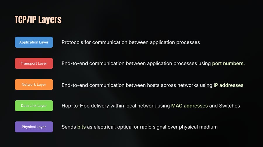
Application Layer
Protocols for communication between application processes
Transport Layer
End-to-end communication between application processes using port numbers.
Network Layer
End-to-end communication between hosts across networks using IP addresses
Data Link Layer
Hop-to-Hop delivery within local network using MAC addresses and Switches
Physical Layer
Sends bits as electrical, optical or radio signal over physical medium
TCP/IP Working
15
Notes
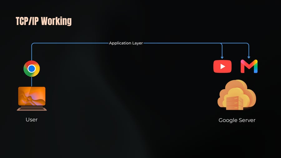
Application Layer
User
Google Server
TCP/IP Working
16
Notes
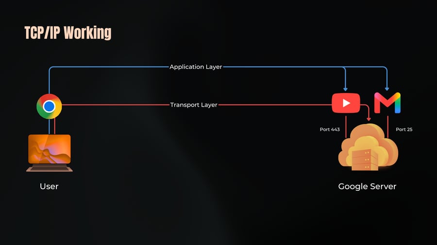
Application Layer
Transport Layer
Port 443
Port 25
User
Google Server
TCP/IP Working
17
Notes
Application Layer
Transport Layer
Port 443
Port 25
Internate Layer
192.0.0.1
142.250.0.0
TCP/IP Working
18
Notes
Application Layer
Transport Layer
Port 443
Port 25
Internate Layer
Data Link
Data Link
Data Link
192.0.0.1
Switch 1
Router 1
Router 2
Switch 2
142.250.0.0
TCP/IP Working
19
Notes
Application
Transport
Internate
Port 443
Port 25
Data Link
Physical
Switch 1
Router 1
Router 2
Switch 2
192.0.0.1
142.250.0.0
Encapsulation
20
Notes
Application Layer
Data
Encapulate
Transport Layer
L4 Header
Data
Encapulate
Network Layer
L3 Header
L4 Header
Data
Encapulate
Data Link Layer
L2 Header
L3 Header
L4 Header
Data
L2 Trailer
Physical Layer
0 1 1 1 0 1 0 1 1 0 0 0 1 1 0 1 1 1 1 0 0 0 0 1 1 1 0 1 0 1 0 1 0 0 1 1 1 1 0 0
Decapsulation
21
Notes
Application Layer
Data
Decapsulate
Transport Layer
L4 Header
Data
Decapsulate
Network Layer
L3 Header
L4 Header
Data
Decapsulate
Data Link Layer
L2 Header
L3 Header
L4 Header
Data
L2 Trailer
Physical Layer
0 1 1 1 0 1 0 1 1 0 0 0 1 1 0 1 1 1 1 0 0 0 0 1 1 1 0 1 0 1 0 1 0 0 1 1 1 1 0 0
Protocal Data Unit
22
Notes
We can use alternative names to describe the message at each stage. These alternative names are called as protocol data units.
A segment or datagram is Layer 4 PDU.
A packet is a Layer 3 PDU
A frame is a Layer 2 PDU.
The contents of each PDU are called payload.
• Segment or Datagram’s payload is application data.
• Packet’s payload is a segment or datagram.
• A frame’s payload is a packet.
Message Delivery
23
Notes
We have covered how the OSI model layers work, how TCP/IP maps to it, how a packet journeys from one end to another.
But there is one question we haven't answered yet - When a device sends data who is it sending to? One device? All devices? A specific group? The nearest one?
These are not the same thing - and the network handles each case differently.
This is what message delivery options are about.
There are four ways to deliver message
i. Unicast
ii. Broadcast
iii. Multicast
iv. Anycast
Types of Message Delivery
24
Notes
unicast
broadcast
multicast
anycast
Unicast - one to one, your Netflix stream, your API call, your SSH session.
Broadcast - one to all. Message in whatsapp group.
Multicast - one to group. Live video stream going to subscribed viewers.
Anycast - one to nearest. DNS Queries routed to the closest server.
Anycast
25
Notes
This one is the most interesting and the least understood.
With anycast, multiple servers around the world share the same IP address.
Example: DNS
When you type a domain name and your device queries a DNS resolver that query often goes to an anycast address.
Cloudflare's famous DNS resolver is 1.1.1.1.
That single IP address is simultaneously hosted on hundreds of servers across the world.
When you query it from Mumbai, you hit a server in Mumbai. When someone queries it from London, they hit a server in London.
Same IP, different physical machines, nearest one wins.
Network Models
26
Notes
The Language of Communication
Need of Models
Who defines Standards..?
OSI Model
TCP/IP Model
Encapulation
Decapsulation
Message Delivery
In the next chapter, we'll understand network devices accross multiple layers.