

On this page
- Network Layer & IP Addressing
- Addressing Systems
- IP Addressing
- IPv4
- IPv6
- Nature of IP
- Private IP
- Private IP
- Public IP
- Public IP
- Dynamic IP
- Static IP
- Dynamic vs Static
- Designing Network
- Subnet
- Classfull Subnet
- Classfull Subnet
- Classless Inter-Domain Routing
- Classless Inter-Domain Routing
- Example - 192.168.1.0/26
- IP Packet Anatomy
- IP Packet Anatomy
- IP Packet Anatomy
- IP Packet Anatomy
- IP Packet Anatomy
- NAT
- Working of NAT
- NAT Example
- NAT Example
- NAT Example
- Types of NAT
- NAT in Practice
- NAT in Practice
- Routing Scenario 1
- Routing Scenario 1
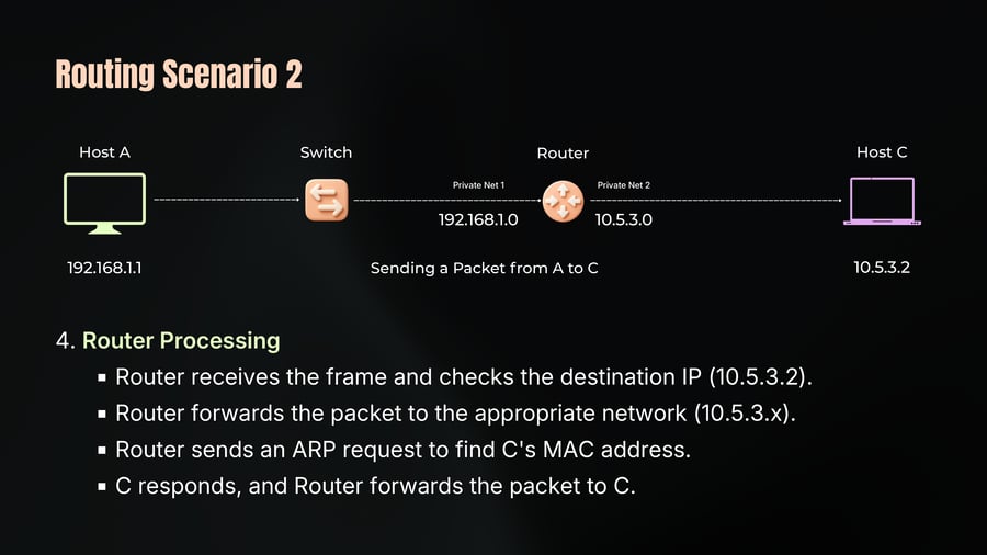
- Routing Scenario 2
- Routing Scenario 2
- Routing Scenario 2
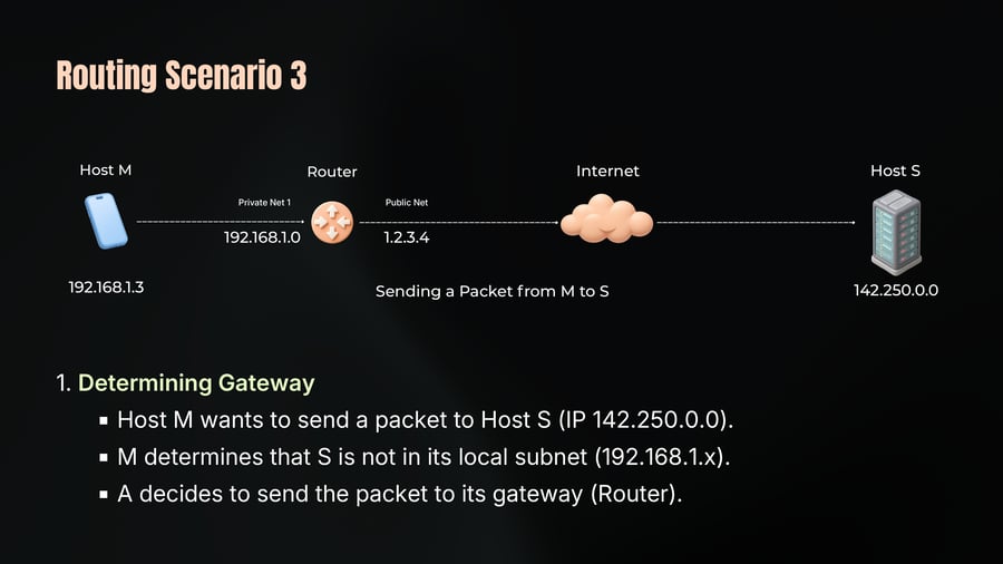
- Routing Scenario 3
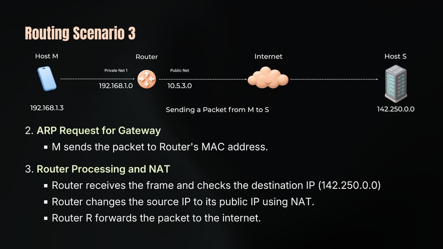
- Routing Scenario 3
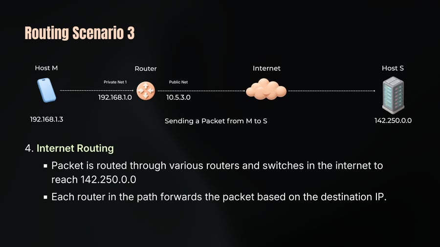
- Routing Scenario 3
- ICMP
- ICMP Messages
- ICMP Limitations
- Ping Utility
- Traceroute Utility
- The Network Layer & IP Addressing
Network Layer & IP Addressing
01
Notes
Chap 4
The Addressing System of the Internet.
Addressing Systems
02
Notes
In previous chapters we covered the physical layer and data link layer. You now know that a MAC address identifies a device on a local network.
But here is the problem. MAC addresses only work locally - within a LAN.
The moment your data needs to leave your local network and travel across the internet to a server in another country - MAC addresses are useless. They are not designed for that.
We need a different addressing system. One that works at a global scale. One that every device on the internet understands. One that routers can use to make decisions about where to send your data.
That system is IP addressing.
IP Addressing
03
Notes
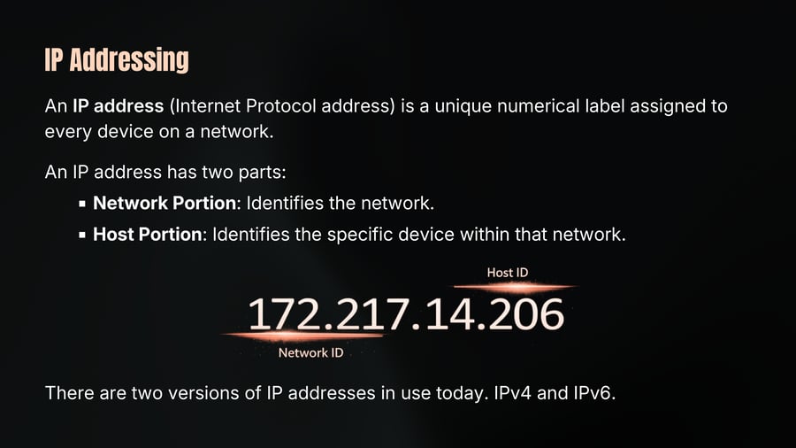
An IP address (Internet Protocol address) is a unique numerical label assigned to every device on a network.
An IP address has two parts:
Network Portion: Identifies the network.
Host Portion: Identifies the specific device within that network.
There are two versions of IP addresses in use today. IPv4 and IPv6.
IPv4
04
Notes
An IPv4 address looks like this - 192.168.1.1
Four numbers separated by dots.
Each number - called an octet, which can range from 0 to 255.
So a full IPv4 address is 32 bits of information, four groups of 8 bits each.
Two to the power of 32 gives us approximately 4.3 billion addresses.
In 1983 when IPv4 was designed - 4.3 billion seemed like more than enough. Nobody imagined billions of smartphones, IoT devices, laptops, and servers all needing unique addresses.
IPv6
05
Notes
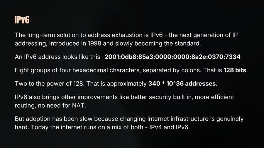
The long-term solution to address exhaustion is IPv6 - the next generation of IP addressing, introduced in 1998 and slowly becoming the standard.
An IPv6 address looks like this- 2001:0db8:85a3:0000:0000:8a2e:0370:7334
Eight groups of four hexadecimal characters, separated by colons. That is 128 bits.
Two to the power of 128. That is approximately 340 * 10^36 addresses.
IPv6 also brings other improvements like better security built in, more efficient routing, no need for NAT.
But adoption has been slow because changing internet infrastructure is genuinely hard. Today the internet runs on a mix of both - IPv4 and IPv6.
Nature of IP
06
Notes
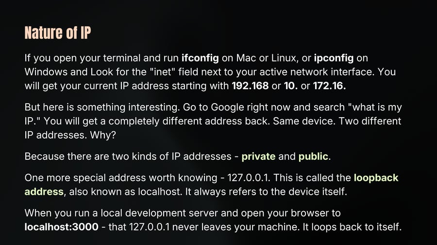
If you open your terminal and run ifconfig on Mac or Linux, or ipconfig on Windows and Look for the "inet" field next to your active network interface. You will get your current IP address starting with 192.168 or 10. or 172.16.
But here is something interesting. Go to Google right now and search "what is my IP." You will get a completely different address back. Same device. Two different IP addresses. Why?
Because there are two kinds of IP addresses - private and public.
One more special address worth knowing - 127.0.0.1. This is called the loopback address, also known as localhost. It always refers to the device itself.
When you run a local development server and open your browser to localhost:3000 - that 127.0.0.1 never leaves your machine. It loops back to itself.
Private IP
07
Notes
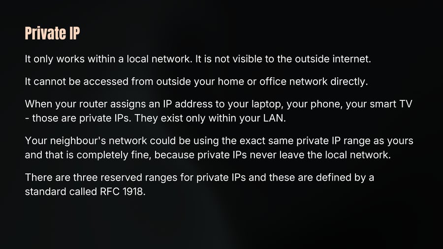
It only works within a local network. It is not visible to the outside internet.
It cannot be accessed from outside your home or office network directly.
When your router assigns an IP address to your laptop, your phone, your smart TV - those are private IPs. They exist only within your LAN.
Your neighbour's network could be using the exact same private IP range as yours and that is completely fine, because private IPs never leave the local network.
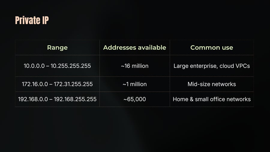
There are three reserved ranges for private IPs and these are defined by a standard called RFC 1918.
Private IP
08
Notes
Range
Addresses available
Common use
10.0.0.0 – 10.255.255.255
~16 million
Large enterprise, cloud VPCs
172.16.0.0 – 172.31.255.255
~1 million
Mid-size networks
192.168.0.0 – 192.168.255.255
~65,000
Home & small office networks
Public IP
09
Notes
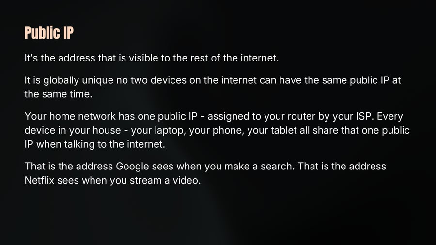
It's the address that is visible to the rest of the internet.
It is globally unique no two devices on the internet can have the same public IP at the same time.
Your home network has one public IP - assigned to your router by your ISP. Every device in your house - your laptop, your phone, your tablet all share that one public IP when talking to the internet.
That is the address Google sees when you make a search. That is the address Netflix sees when you stream a video.
Public IP
10
Notes
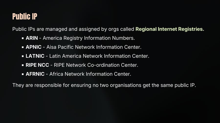
Public IPs are managed and assigned by orgs called Regional Internet Registries.
ARIN - America Registry Information Numbers.
APNIC - Aisa Pacific Network Information Center.
LATNIC - Latin America Network Information Center.
RIPE NCC - RIPE Network Co-ordination Center.
AFRNIC - Africa Network Information Center.
They are responsible for ensuring no two organisations get the same public IP.
Dynamic IP
11
Notes
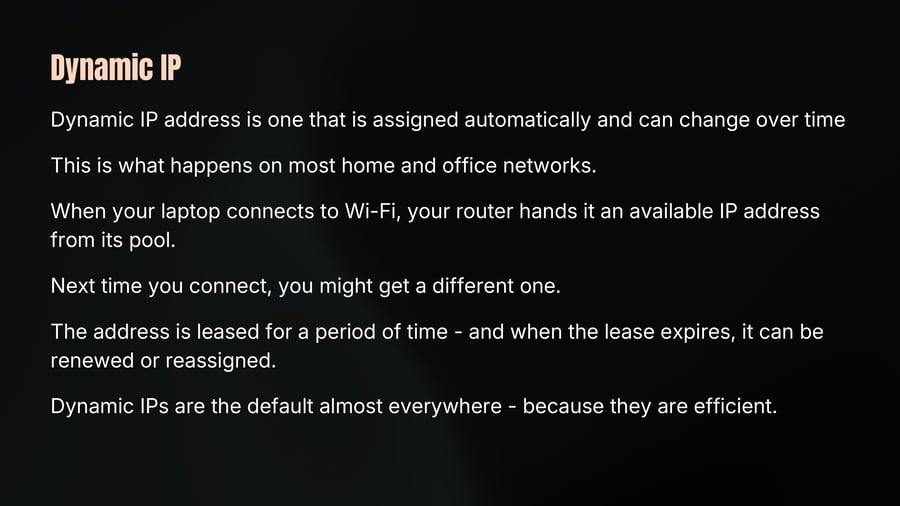
Dynamic IP address is one that is assigned automatically and can change over time
This is what happens on most home and office networks.
When your laptop connects to Wi-Fi, your router hands it an available IP address from its pool.
Next time you connect, you might get a different one.
The address is leased for a period of time - and when the lease expires, it can be renewed or reassigned.
Dynamic IPs are the default almost everywhere - because they are efficient.
Static IP
12
Notes
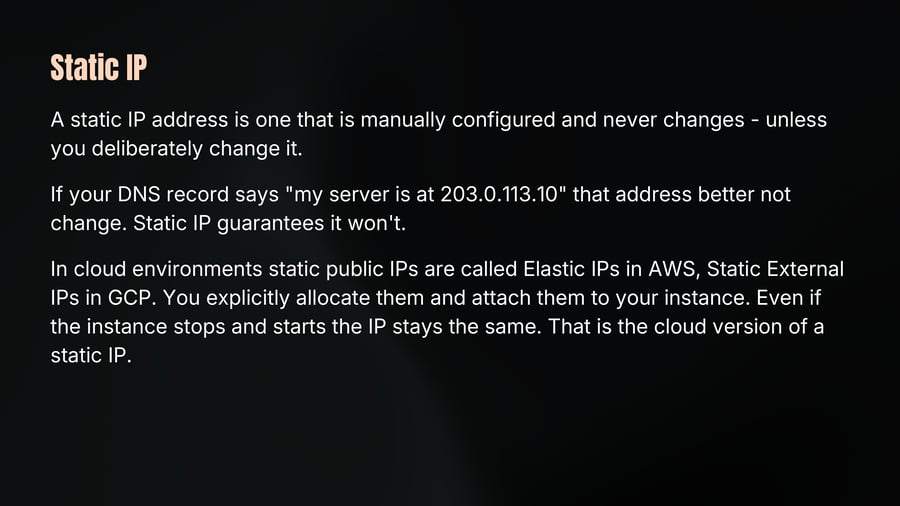
A static IP address is one that is manually configured and never changes - unless you deliberately change it.
If your DNS record says "my server is at 203.0.113.10" that address better not change. Static IP guarantees it won't.
In cloud environments static public IPs are called Elastic IPs in AWS, Static External IPs in GCP. You explicitly allocate them and attach them to your instance. Even if the instance stops and starts the IP stays the same. That is the cloud version of a static IP.
Dynamic vs Static
13

Notes
Dynamic IP
Assigned automatically by DHCP
Can change on reconnet
Default for home network
Not suitable for hosting servers
Static IP
Manually set / permanently reserved
Never Changes
Used for server, routers, databases
Essentail for DNS & public services
If something needs to find you - you need a static IP. But if you are just browsing the internet, streaming video, or connecting to cloud services - dynamic is perfectly fine.
This is why your laptop has a dynamic IP but Youtube's servers have static IPs.
Designing Network
14
Notes
Imagine you work at a company with 500 people - engineers, HR, finance, sales all sitting in the same office building, all connected to the same network.
Now here's the scary part.
Every time the finance team processes payroll, or approves a banking transaction that data is traveling across the same network that every engineer and every salesperson is on. Anyone with the right tools can see it.
That's not just a security nightmare. It's also a performance problem. Every device is generating constant network noise, and every single broadcast packet from any one device reaches all 500 others.
So what's the fix? Subnetting.
Subnet
15
Notes
A subnet, short for subnetwork, is a logical division of a larger IP network into smaller, isolated segments.
Every subnet is defined by two things:
A network address - which identifies the subnet itself
A subnet mask - which determines whether any given IP address belongs to that subnet
Subnet mask determines if an IP address is within the same subnet.
The subnet mask essentially draws a line, everything to the left of the line is the network, everything to the right is the host.
There are two types of Subnet Mask: Classfull and Classless.
Classfull Subnet
16
Notes
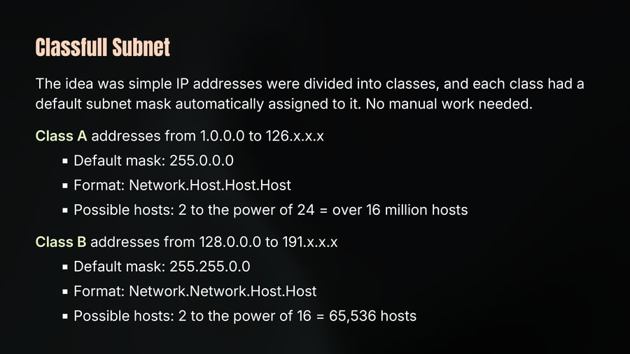
The idea was simple IP addresses were divided into classes, and each class had a default subnet mask automatically assigned to it. No manual work needed.
Class A addresses from 1.0.0.0 to 126.x.x.x
Default mask: 255.0.0.0
Format: Network.Host.Host.Host
Possible hosts: 2 to the power of 24 = over 16 million hosts
Class B addresses from 128.0.0.0 to 191.x.x.x
Default mask: 255.255.0.0
Format: Network.Network.Host.Host
Possible hosts: 2 to the power of 16 = 65,536 hosts
Classfull Subnet
17
Notes
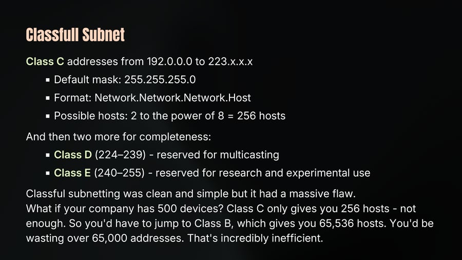
Class C addresses from 192.0.0.0 to 223.x.x.x
Default mask: 255.255.255.0
Format: Network.Network.Network.Host
Possible hosts: 2 to the power of 8 = 256 hosts
And then two more for completeness:
Class D (224–239) - reserved for multicasting
Class E (240–255) - reserved for research and experimental use
Classful subnetting was clean and simple but it had a massive flaw.
What if your company has 500 devices? Class C only gives you 256 hosts - not enough. So you'd have to jump to Class B, which gives you 65,536 hosts. You'd be wasting over 65,000 addresses. That's incredibly inefficient.
Classless Inter-Domain Routing
18
Notes
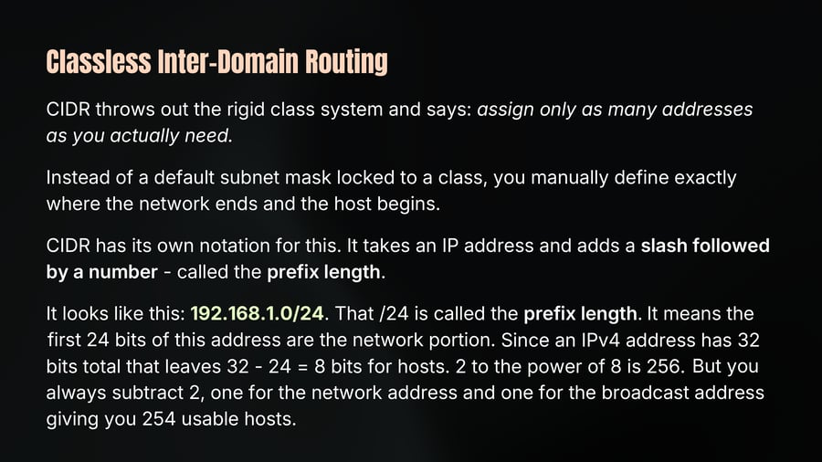
CIDR throws out the rigid class system and says: assign only as many addresses as you actually need.
Instead of a default subnet mask locked to a class, you manually define exactly where the network ends and the host begins.
CIDR has its own notation for this. It takes an IP address and adds a slash followed by a number - called the prefix length.
It looks like this: 192.168.1.0/24. That /24 is called the prefix length. It means the first 24 bits of this address are the network portion. Since an IPv4 address has 32 bits total that leaves 32 - 24 = 8 bits for hosts. 2 to the power of 8 is 256. But you always subtract 2, one for the network address and one for the broadcast address giving you 254 usable hosts.
Classless Inter-Domain Routing
19
Notes
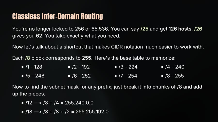
You're no longer locked to 256 or 65,536. You can say /25 and get 126 hosts. /26 gives you 62. You take exactly what you need.
Now let's talk about a shortcut that makes CIDR notation much easier to work with.
Each /8 block corresponds to 255. Here's the base table to memorize:
/1 - 128
/2 - 192
/3 - 224
/4 - 240
/5 - 248
/6 - 252
/7 - 254
/8 - 255
Now to find the subnet mask for any prefix, just break it into chunks of /8 and add up the pieces.
/12 —> /8 + /4 = 255.240.0.0
/18 —> /8 + /8 + /2 = 255.255.192.0
Example - 192.168.1.0/26
20
Notes
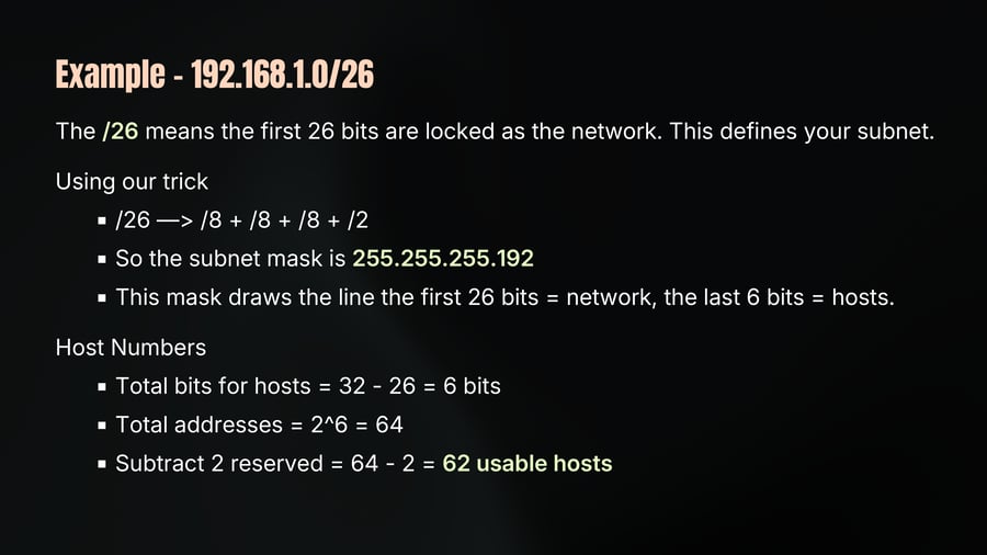
The /26 means the first 26 bits are locked as the network. This defines your subnet.
Using our trick
/26 —> /8 + /8 + /8 + /2
So the subnet mask is 255.255.255.192
This mask draws the line the first 26 bits = network, the last 6 bits = hosts.
Host Numbers
Total bits for hosts = 32 - 26 = 6 bits
Total addresses = 2^6 = 64
Subtract 2 reserved = 64 - 2 = 62 usable hosts
IP Packet Anatomy
21
Notes
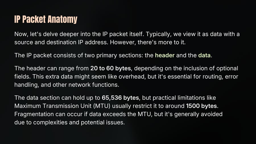
Now, let's delve deeper into the IP packet itself. Typically, we view it as data with a source and destination IP address. However, there's more to it.
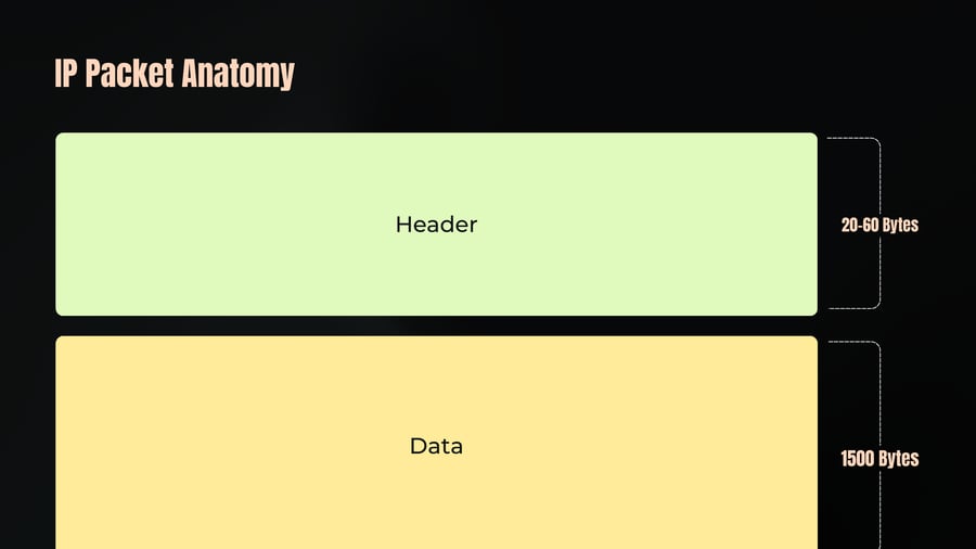
The IP packet consists of two primary sections: the header and the data.
The header can range from 20 to 60 bytes, depending on the inclusion of optional fields. This extra data might seem like overhead, but it's essential for routing, error handling, and other network functions.
The data section can hold up to 65,536 bytes, but practical limitations like Maximum Transmission Unit (MTU) usually restrict it to around 1500 bytes. Fragmentation can occur if data exceeds the MTU, but it's generally avoided due to complexities and potential issues.
IP Packet Anatomy
22
Notes
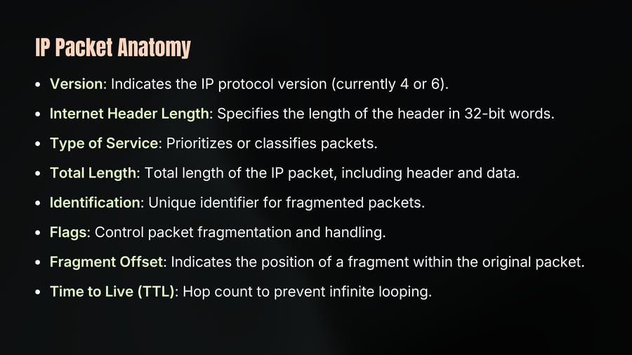
Version: Indicates the IP protocol version (currently 4 or 6).
Internet Header Length: Specifies the length of the header in 32-bit words.
Type of Service: Prioritizes or classifies packets.
Total Length: Total length of the IP packet, including header and data.
Identification: Unique identifier for fragmented packets.
Flags: Control packet fragmentation and handling.
Fragment Offset: Indicates the position of a fragment within the original packet.
Time to Live (TTL): Hop count to prevent infinite looping.
IP Packet Anatomy
23
Notes
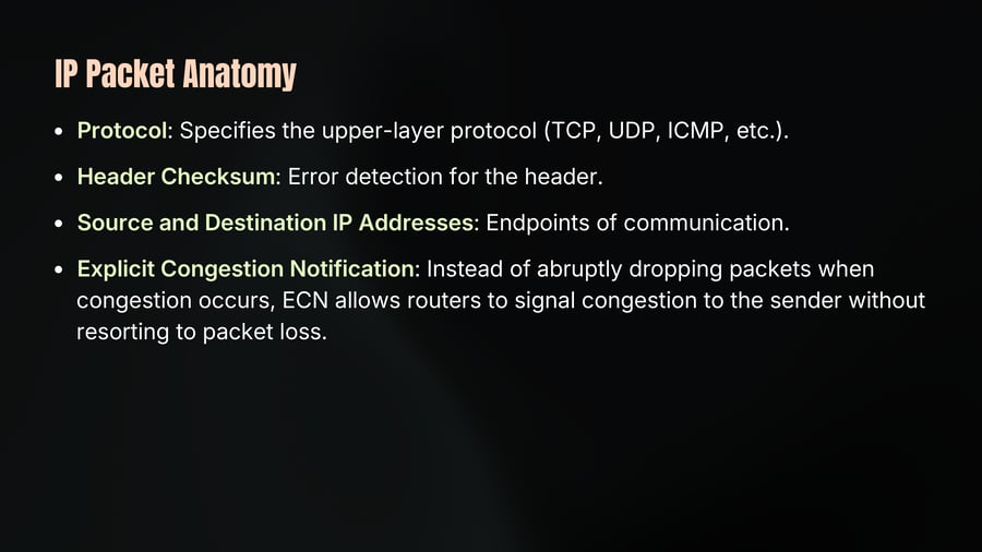
Protocol: Specifies the upper-layer protocol (TCP, UDP, ICMP, etc.).
Header Checksum: Error detection for the header.
Source and Destination IP Addresses: Endpoints of communication.
Explicit Congestion Notification: Instead of abruptly dropping packets when congestion occurs, ECN allows routers to signal congestion to the sender without resorting to packet loss.
IP Packet Anatomy
24
Notes
Header
20-60 Bytes
Data
1500 Bytes
IP Packet Anatomy
25
Notes
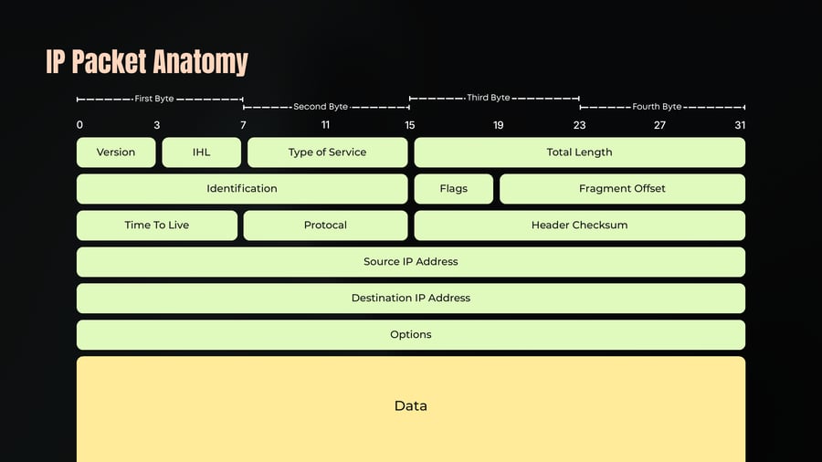
First Byte
Second Byte
Third Byte
Fourth Byte
0 3 7 11 15 19 23 27 31
Version
IHL
Type of Service
Total Length
Identification
Flags
Fragment Offset
Time To Live
Protocal
Header Checksum
Source IP Address
Destination IP Address
Options
Data
NAT
26
Notes
NAT stands for Network Address Translation.
NAT was developed as a solution to the problem of IPv4 address exhaustion.
While IPv4 allows for about 4.3 billion unique addresses, the rapid growth of the internet quickly showed that this number was insufficient.
IPv6 offers a solution with a much larger address space, but the transition to IPv6 is complex and ongoing.
NAT allows multiple devices with private IPs to share a single public IP when communicating with the internet.
Working of NAT
27
Notes
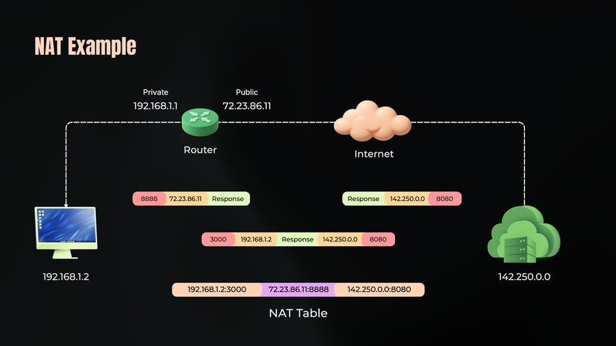
NAT table maps internal (private) IP addresses and ports to external (public) IP addresses and ports.
Process:
Your home network has multiple devices: laptops, smartphones, smart TVs.
Each device has a private IP address (e.g., 192.168.1.x).
All devices share the same public IP address assigned to your router by your Internet Service Provider (ISP).
When a device sends data to the internet, the router changes the private IP address to its public IP address and records this mapping in the NAT table.
When a response is received, the router uses the NAT table to forward the data to the correct device.
NAT Example
28
Notes
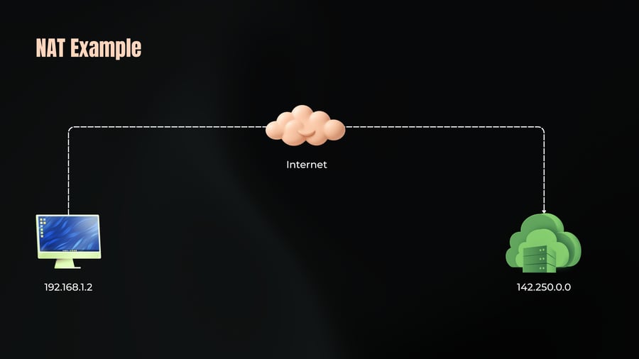
Internet
192.168.1.2
142.250.0.0
NAT Example
29
Notes
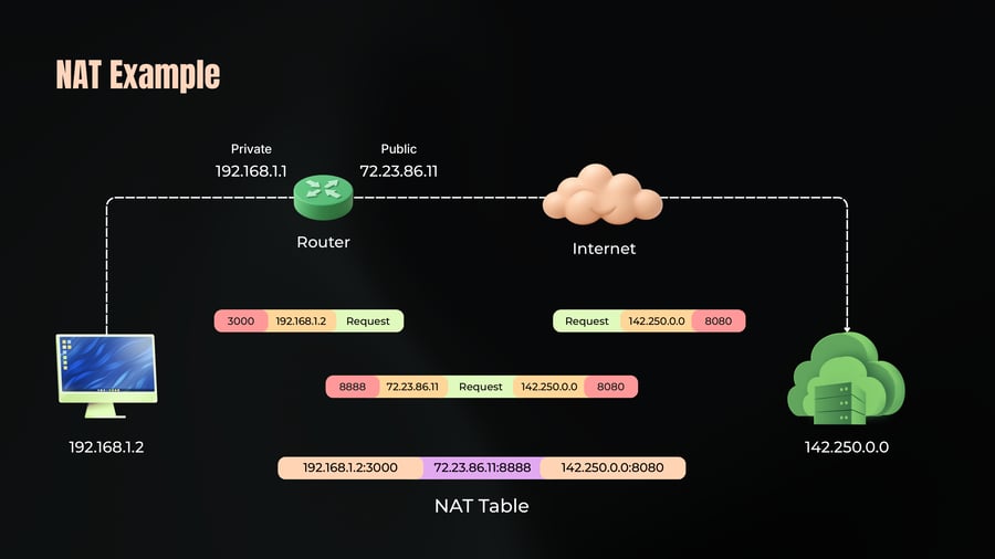
Private
192.168.1.1
Public
72.23.86.11
Router
Internet
3000 192.168.1.2 Request
Request 142.250.0.0 8080
8888 72.23.86.11 Request 142.250.0.0 8080
192.168.1.2
142.250.0.0
192.168.1.2:3000 72.23.86.11:8888 142.250.0.0:8080
NAT Table
NAT Example
30
Notes
Private
Public
192.168.1.1
72.23.86.11
Router
Internet
8888 72.23.86.11 Response
Response 142.250.0.0 8080
3000 192.168.1.2 Response 142.250.0.0 8080
192.168.1.2
142.250.0.0
192.168.1.2:3000 72.23.86.11:8888 142.250.0.0:8080
NAT Table
Types of NAT
31
Notes
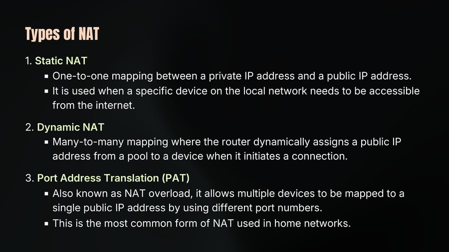
1. Static NAT
One-to-one mapping between a private IP address and a public IP address.
It is used when a specific device on the local network needs to be accessible from the internet.
2. Dynamic NAT
Many-to-many mapping where the router dynamically assigns a public IP address from a pool to a device when it initiates a connection.
3. Port Address Translation (PAT)
Also known as NAT overload, it allows multiple devices to be mapped to a single public IP address by using different port numbers.
This is the most common form of NAT used in home networks.
NAT in Practice
32
Notes
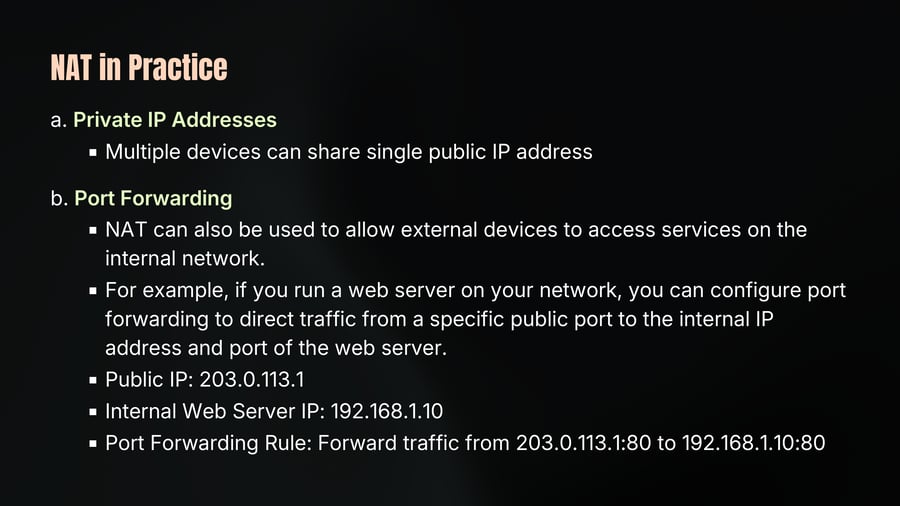
a. Private IP Addresses
Multiple devices can share single public IP address
b. Port Forwarding
NAT can also be used to allow external devices to access services on the internal network.
For example, if you run a web server on your network, you can configure port forwarding to direct traffic from a specific public port to the internal IP address and port of the web server.
Public IP: 203.0.113.1
Internal Web Server IP: 192.168.1.10
Port Forwarding Rule: Forward traffic from 203.0.113.1:80 to 192.168.1.10:80
NAT in Practice
33
Notes
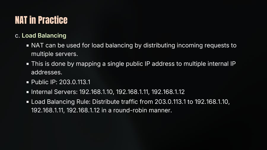
c. Load Balancing
NAT can be used for load balancing by distributing incoming requests to multiple servers.
This is done by mapping a single public IP address to multiple internal IP addresses.
Public IP: 203.0.113.1
Internal Servers: 192.168.1.10, 192.168.1.11, 192.168.1.12
Load Balancing Rule: Distribute traffic from 203.0.113.1 to 192.168.1.10, 192.168.1.11, 192.168.1.12 in a round-robin manner.
Routing Scenario 1
34
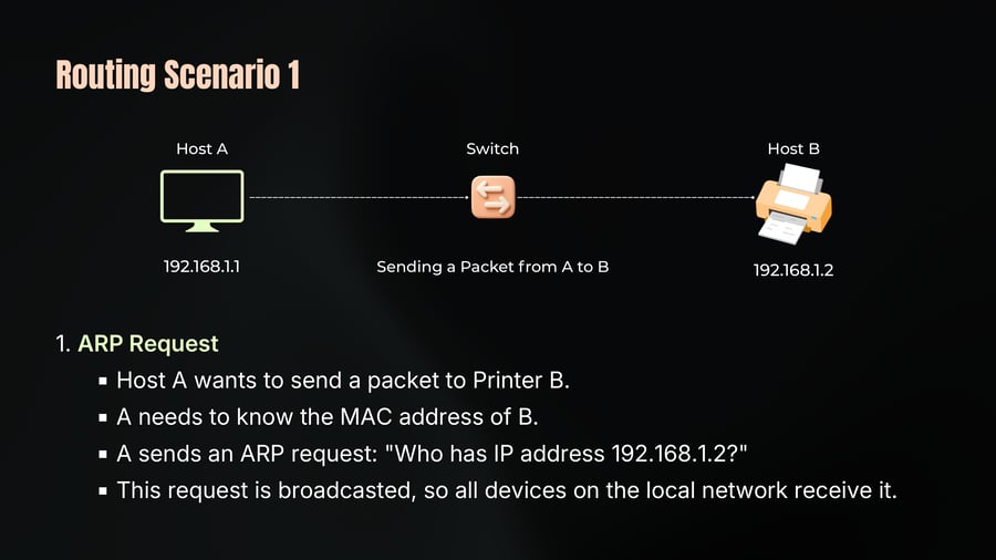
Notes
Host A
Switch
Host B
192.168.1.1
Sending a Packet from A to B
192.168.1.2
1. ARP Request
Host A wants to send a packet to Printer B.
A needs to know the MAC address of B.
A sends an ARP request: "Who has IP address 192.168.1.2?"
This request is broadcasted, so all devices on the local network receive it.
Routing Scenario 1
35
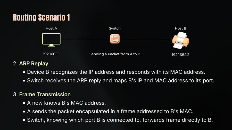
Notes
Host A
Switch
Host B
192.168.1.1
Sending a Packet from A to B
192.168.1.2
2. ARP Replay
Device B recognizes the IP address and responds with its MAC address.
Switch receives the ARP reply and maps B's IP and MAC address to its port.
3. Frame Transmission
A now knows B's MAC address.
A sends the packet encapsulated in a frame addressed to B's MAC.
Switch, knowing which port B is connected to, forwards frame directly to B.
Routing Scenario 2
36
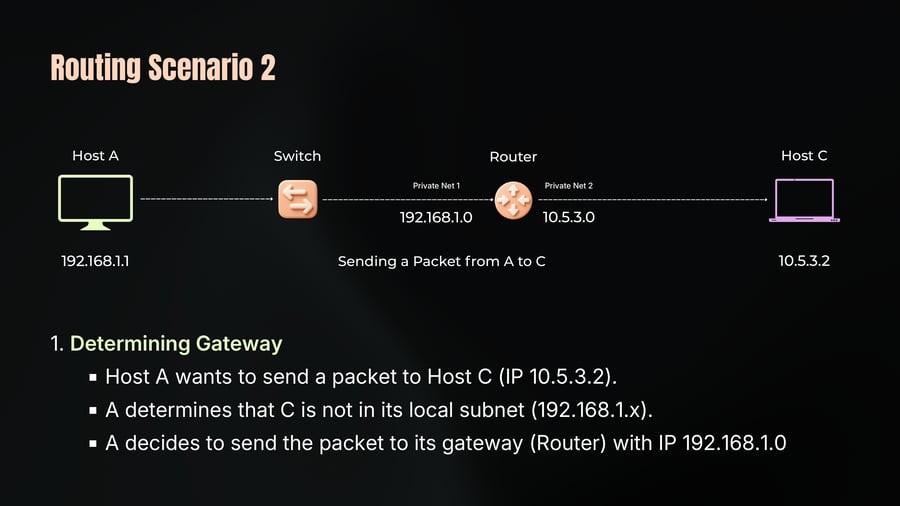
Notes
Host A
Switch
Router
Host C
Private Net 1
Private Net 2
192.168.1.0
10.5.3.0
192.168.1.1
Sending a Packet from A to C
10.5.3.2
1. Determining Gateway
Host A wants to send a packet to Host C (IP 10.5.3.2).
A determines that C is not in its local subnet (192.168.1.x).
A decides to send the packet to its gateway (Router) with IP 192.168.1.0
Routing Scenario 2
37
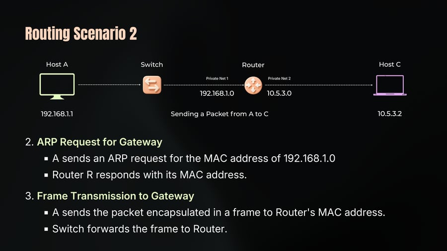
Notes
Host A
Switch
Router
Host C
Private Net 1
Private Net 2
192.168.1.0
10.5.3.0
192.168.1.1
Sending a Packet from A to C
10.5.3.2
2. ARP Request for Gateway
A sends an ARP request for the MAC address of 192.168.1.0
Router R responds with its MAC address.
3. Frame Transmission to Gateway
A sends the packet encapsulated in a frame to Router's MAC address.
Switch forwards the frame to Router.
Routing Scenario 2
38
Notes
Sending a Packet from A to C
4. Router Processing
Router receives the frame and checks the destination IP (10.5.3.2).
Router forwards the packet to the appropriate network (10.5.3.x).
Router sends an ARP request to find C's MAC address.
C responds, and Router forwards the packet to C.
Routing Scenario 3
39
Notes
Host M
Router
Internet
Host S
Private Net 1
Public Net
192.168.1.0
1.2.3.4
192.168.1.3
Sending a Packet from M to S
142.250.0.0
1. Determining Gateway
Host M wants to send a packet to Host S (IP 142.250.0.0).
M determines that S is not in its local subnet (192.168.1.x).
A decides to send the packet to its gateway (Router).
Routing Scenario 3
40
Notes
Host M
Router
Internet
Host S
Private Net 1
Public Net
192.168.1.0
10.5.3.0
192.168.1.3
Sending a Packet from M to S
142.250.0.0
2. ARP Request for Gateway
M sends the packet to Router's MAC address.
3. Router Processing and NAT
Router receives the frame and checks the destination IP (142.250.0.0)
Router changes the source IP to its public IP using NAT.
Router R forwards the packet to the internet.
Routing Scenario 3
41
Notes
Host M
Router
Internet
Host S
Private Net 1
Public Net
192.168.1.0
10.5.3.0
192.168.1.3
Sending a Packet from M to S
142.250.0.0
4. Internet Routing
Packet is routed through various routers and switches in the internet to reach 142.250.0.0
Each router in the path forwards the packet based on the destination IP.
ICMP
42
Notes
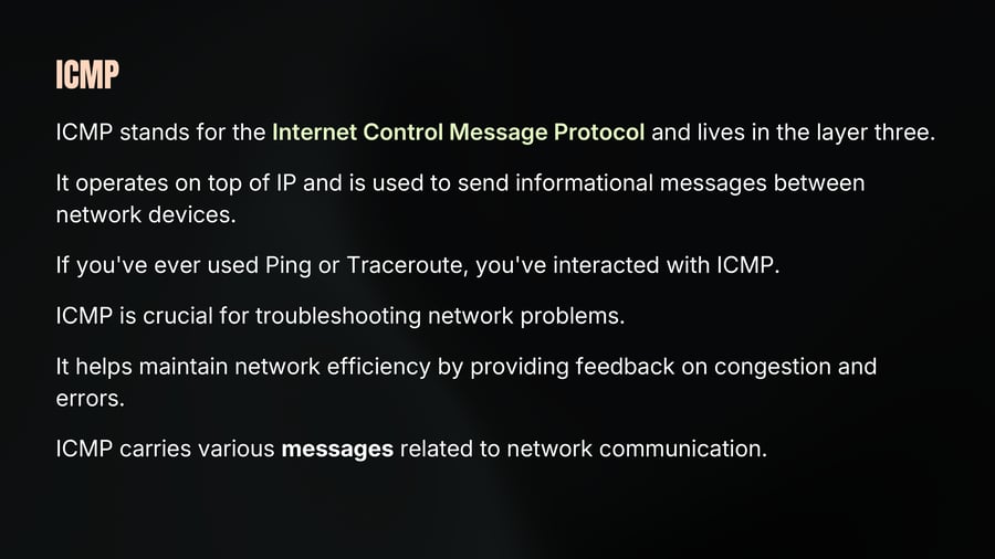
ICMP stands for the Internet Control Message Protocol and lives in the layer three.
It operates on top of IP and is used to send informational messages between network devices.
If you've ever used Ping or Traceroute, you've interacted with ICMP.
ICMP is crucial for troubleshooting network problems.
It helps maintain network efficiency by providing feedback on congestion and errors.
ICMP carries various messages related to network communication.
ICMP Messages
43
Notes
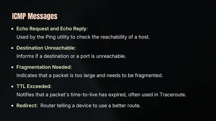
Echo Request and Echo Reply:
Used by the Ping utility to check the reachability of a host.
Destination Unreachable:
Informs if a destination or a port is unreachable.
Fragmentation Needed:
Indicates that a packet is too large and needs to be fragmented.
TTL Exceeded:
Notifies that a packet's time-to-live has expired, often used in Traceroute.
Redirect: Router telling a device to use a better route.
ICMP Limitations
44
Notes
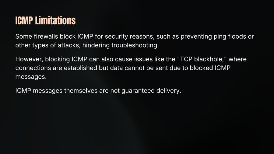
Some firewalls block ICMP for security reasons, such as preventing ping floods or other types of attacks, hindering troubleshooting.
However, blocking ICMP can also cause issues like the "TCP blackhole," where connections are established but data cannot be sent due to blocked ICMP messages.
ICMP messages themselves are not guaranteed delivery.
Ping Utility
45
Notes
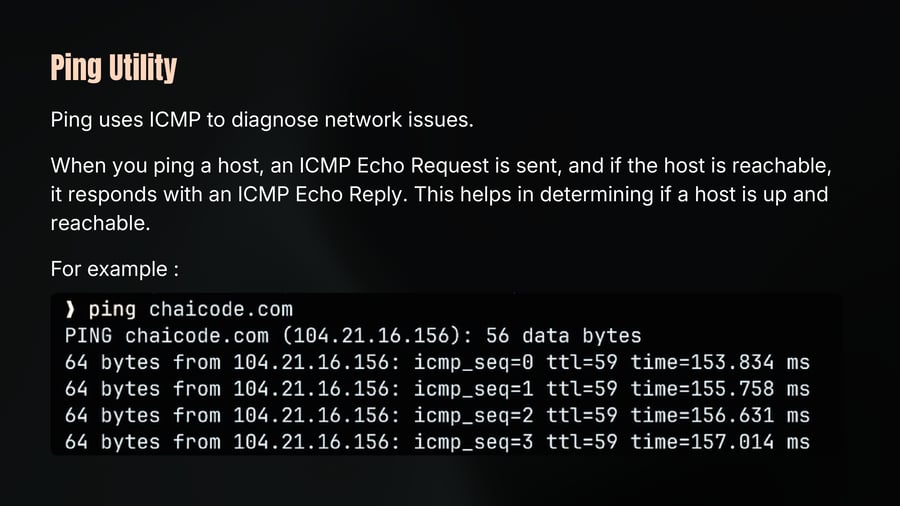
Ping uses ICMP to diagnose network issues.
When you ping a host, an ICMP Echo Request is sent, and if the host is reachable, it responds with an ICMP Echo Reply. This helps in determining if a host is up and reachable.
For example :
❯ ping chaicode.com
PING chaicode.com (104.21.16.156): 56 data bytes
64 bytes from 104.21.16.156: icmp_seq=0 ttl=59 time=153.834 ms
64 bytes from 104.21.16.156: icmp_seq=1 ttl=59 time=155.758 ms
64 bytes from 104.21.16.156: icmp_seq=2 ttl=59 time=156.631 ms
64 bytes from 104.21.16.156: icmp_seq=3 ttl=59 time=157.014 ms
Traceroute Utility
46
Notes
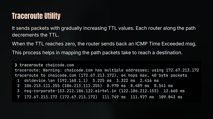
It sends packets with gradually increasing TTL values. Each router along the path decrements the TTL.
When the TTL reaches zero, the router sends back an ICMP Time Exceeded msg.
This process helps in mapping the path packets take to reach a destination.
The Network Layer & IP Addressing
47
Notes
The Addressing System of the Internet.
IP Addressing
Subnet & CIDR
IPv4 and IPv6
IP Packet
Private and Public IP
NAT and Routing Scenarios
Static and Dynamic IP
ICMP Protocol
In the next chapter, we'll understand end to end trasportation of data.